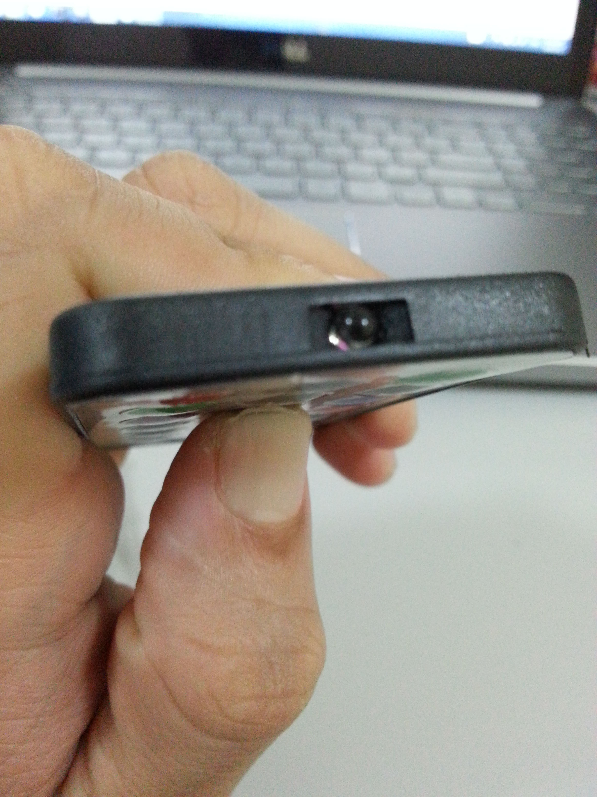
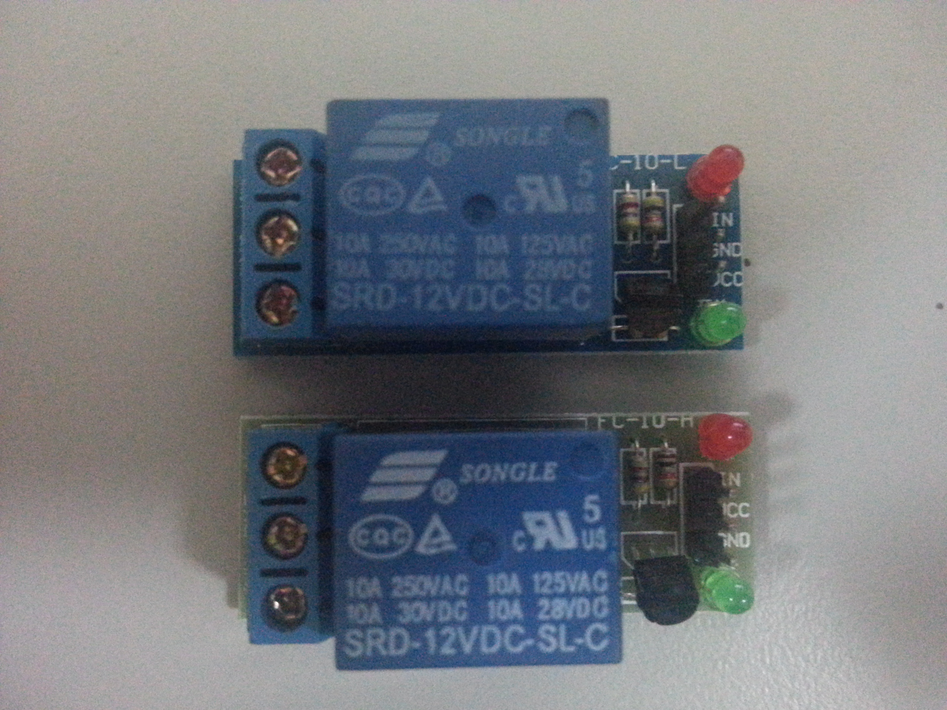
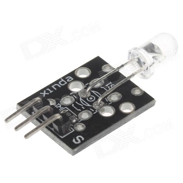
 I got my IR emitter module from 37-in-1 sensor module kit at dx.com. This kit includes a IR emitter and IR receiver, along with many other sensors and controller, but without the mp3 remote controller.
At the time of writing, dx.com have a new product pack where it comes with a mp3 remote controller, infrared receiver module and an extra infrared emitter module (for sending). The price is only usd 5.80.
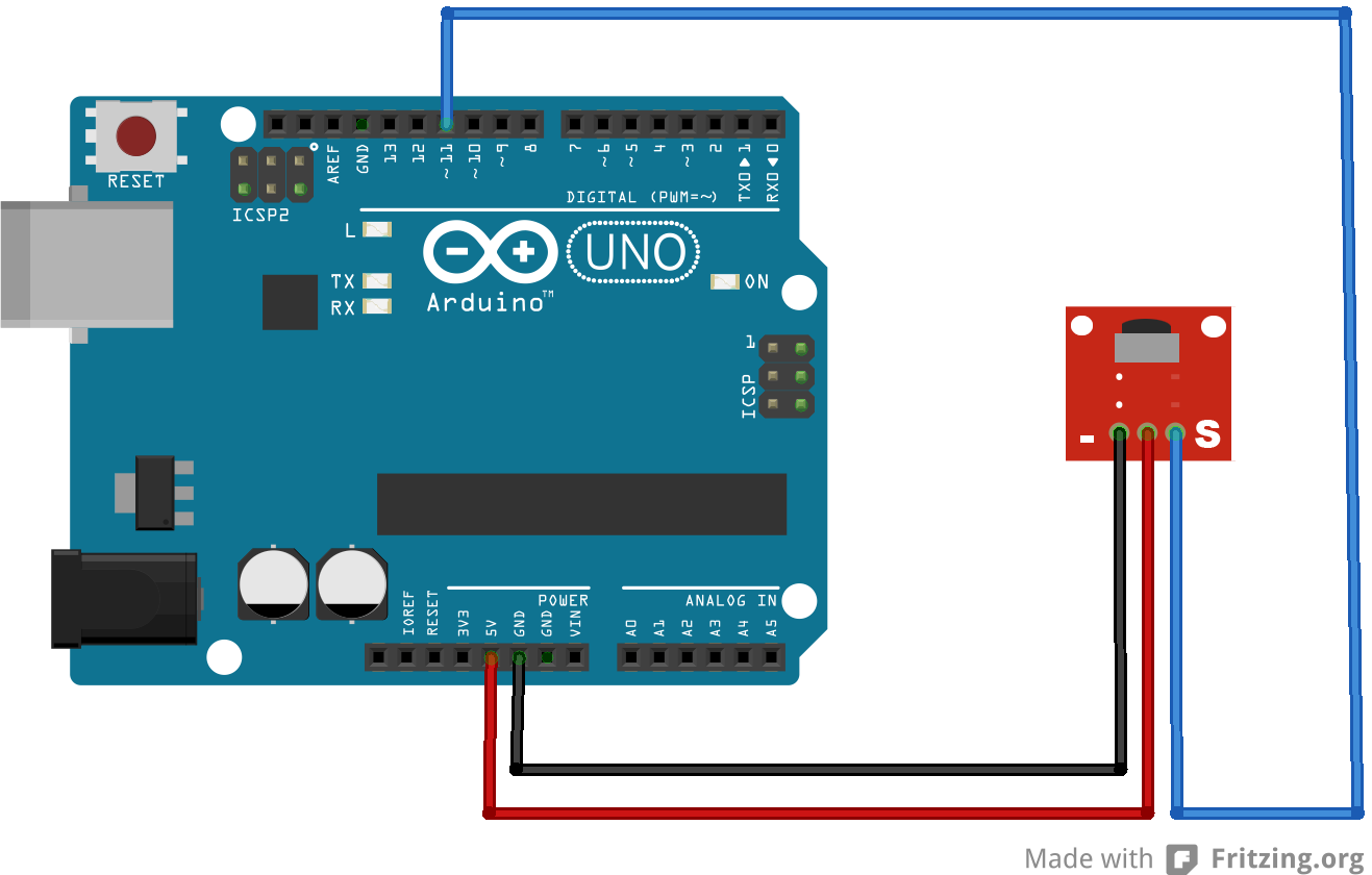
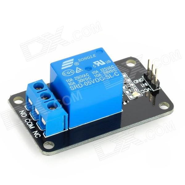
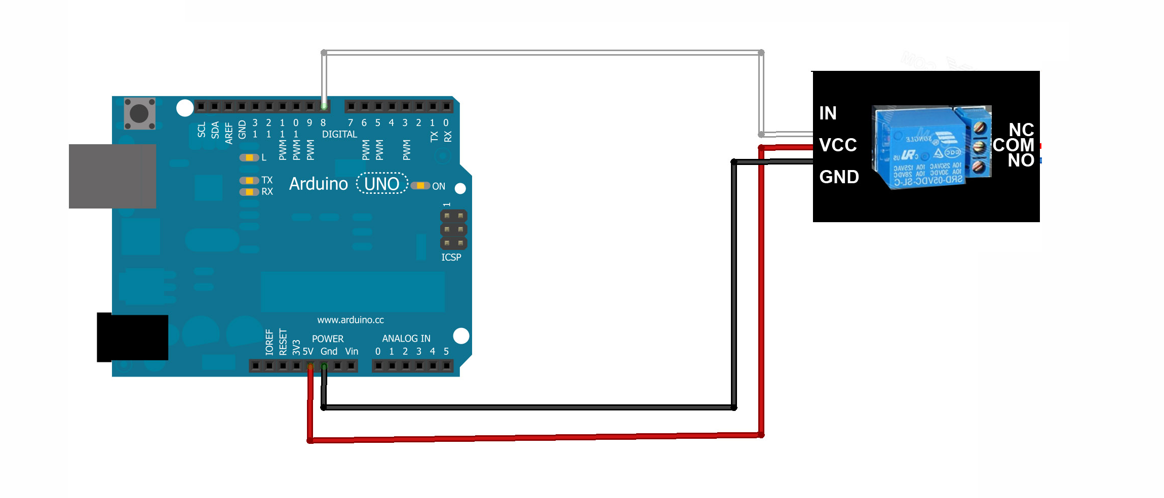
Construct the circuit
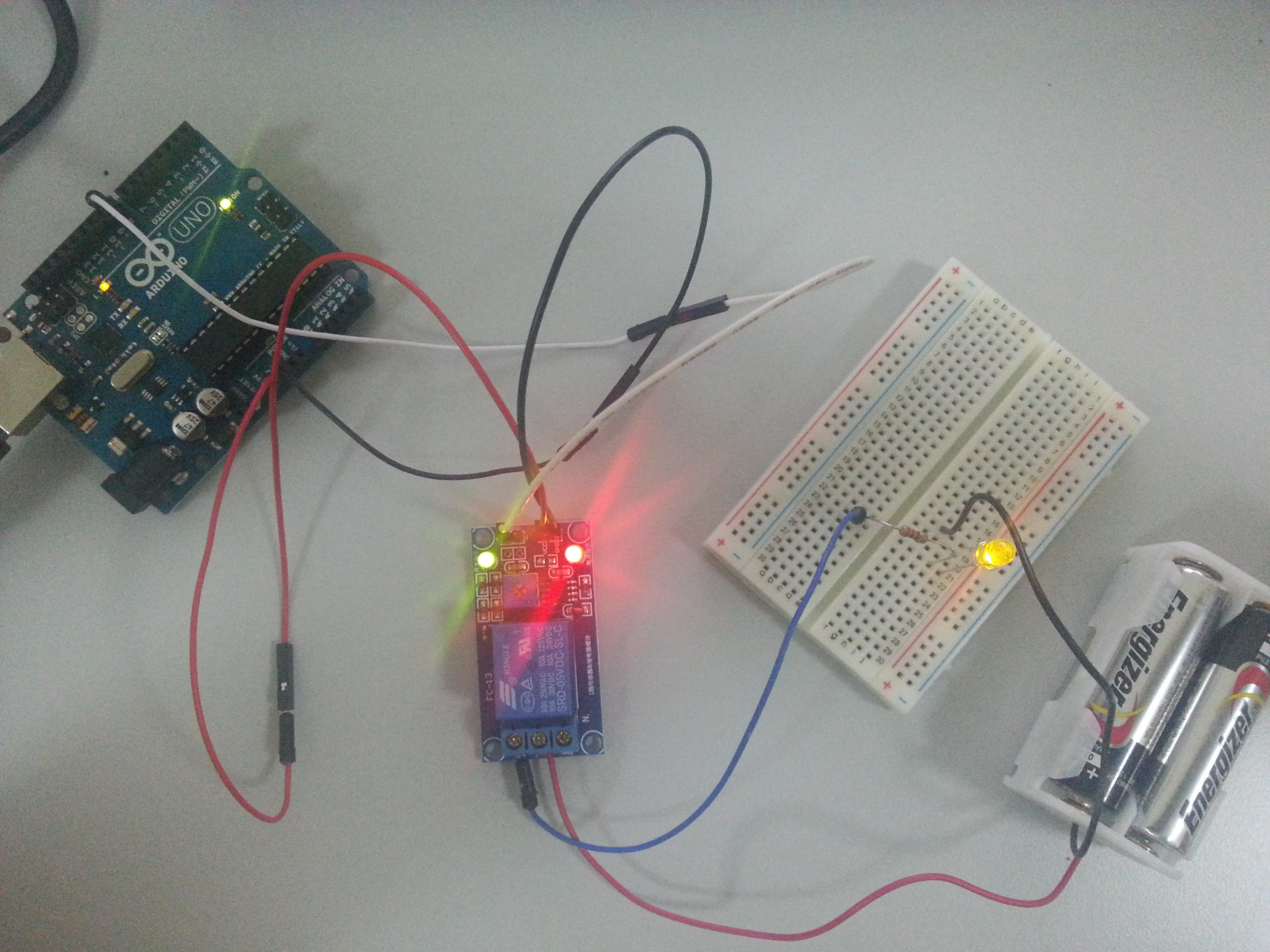
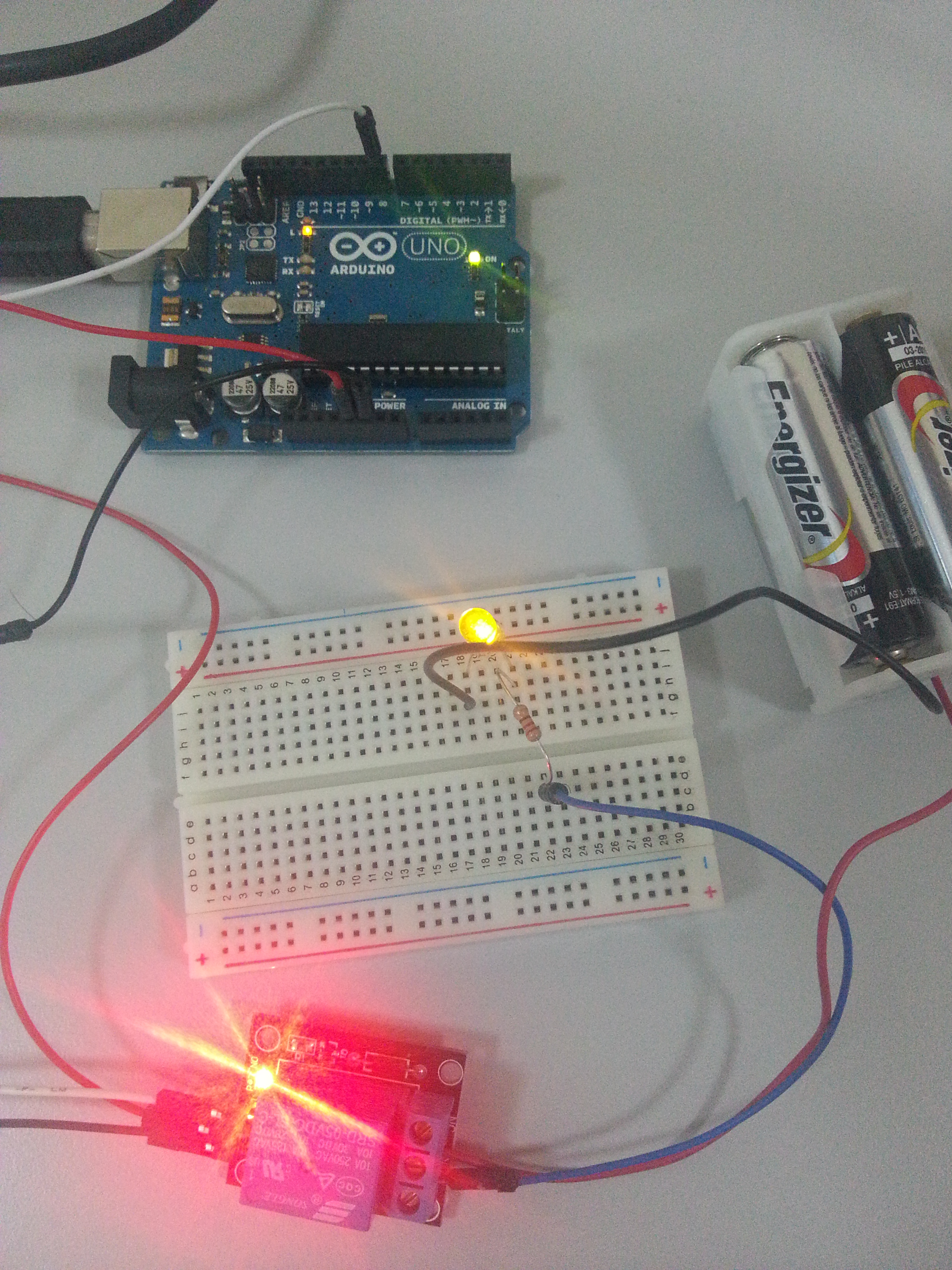
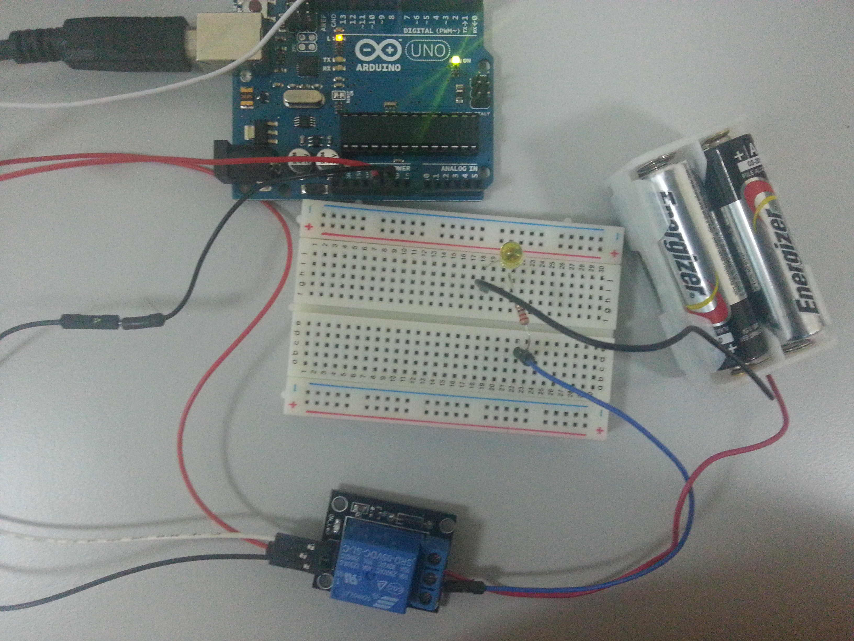
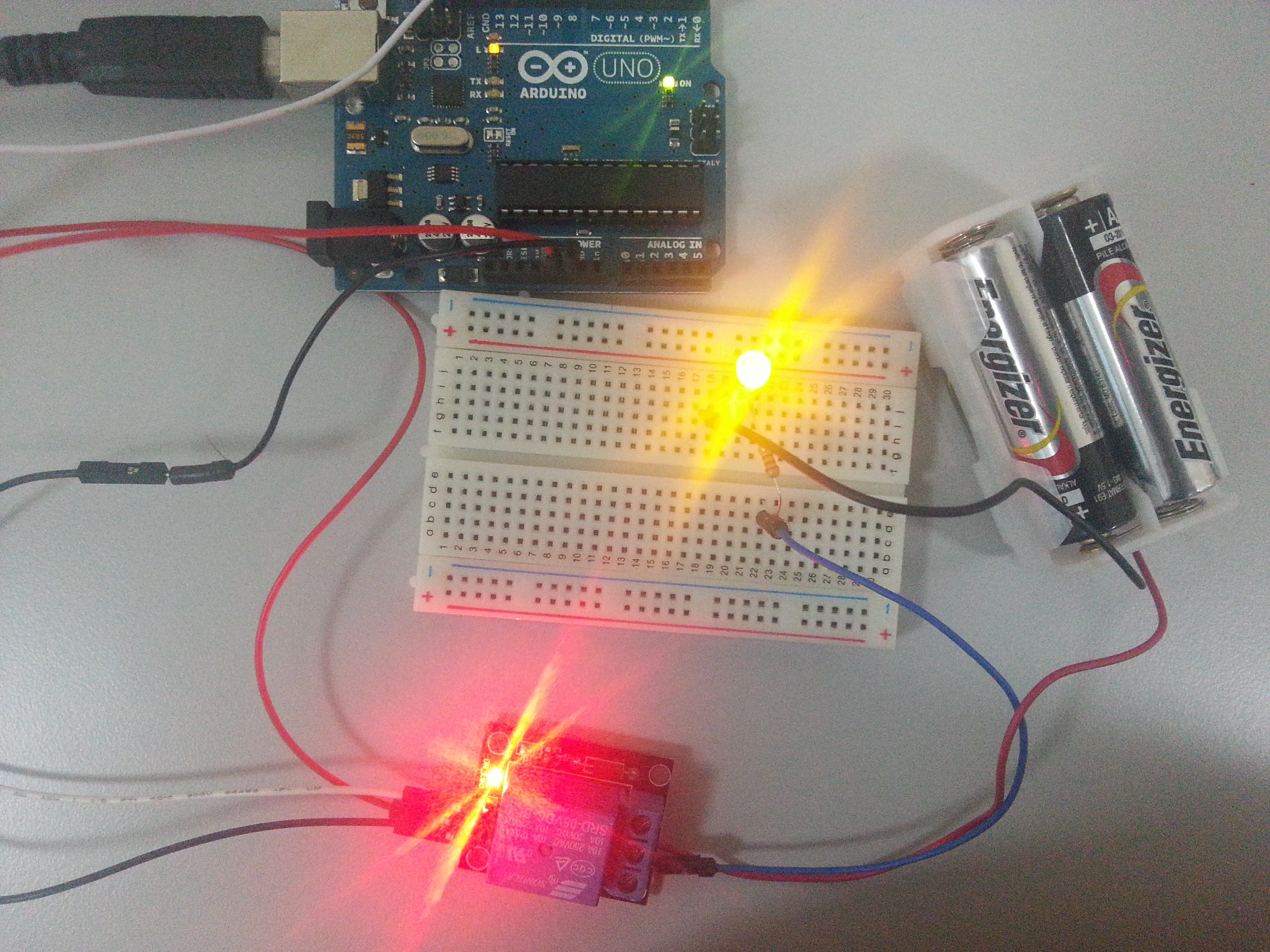
It is very simple, just connect your emitter module, the – pin to GND (ground), S pin to pin 3 on arduino. Leave the center pin unconnected.
The following code will send the signal in NEC hex format of value ‘0xFF18E7’, which is equal to button 2 of the mp3 controller.
I got my IR emitter module from 37-in-1 sensor module kit at dx.com. This kit includes a IR emitter and IR receiver, along with many other sensors and controller, but without the mp3 remote controller.
At the time of writing, dx.com have a new product pack where it comes with a mp3 remote controller, infrared receiver module and an extra infrared emitter module (for sending). The price is only usd 5.80.
Construct the circuit
It is very simple, just connect your emitter module, the – pin to GND (ground), S pin to pin 3 on arduino. Leave the center pin unconnected.
The following code will send the signal in NEC hex format of value ‘0xFF18E7’, which is equal to button 2 of the mp3 controller.
|
1 2 3 4 5 6 7 8 9 10 11 12 13 14 15 16 |
#include <IRremote.h> IRsend irsend; void setup() { Serial.begin(9600); } void loop() { Serial.println("send ir signal"); irsend.sendNEC(0xFF18E7, 32); delay(100); } |
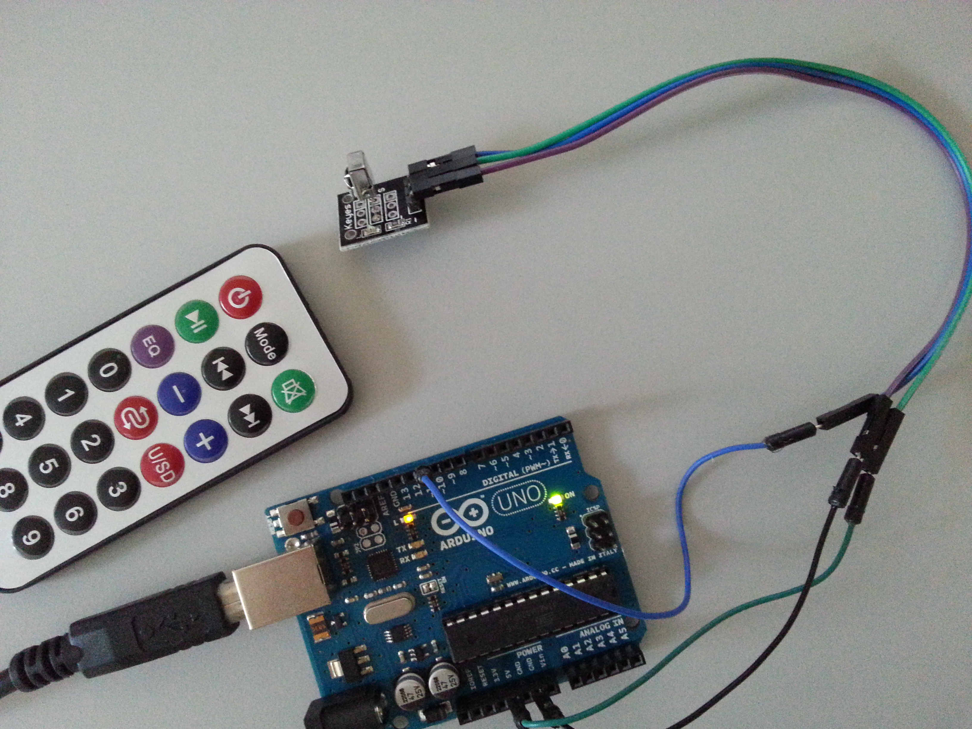
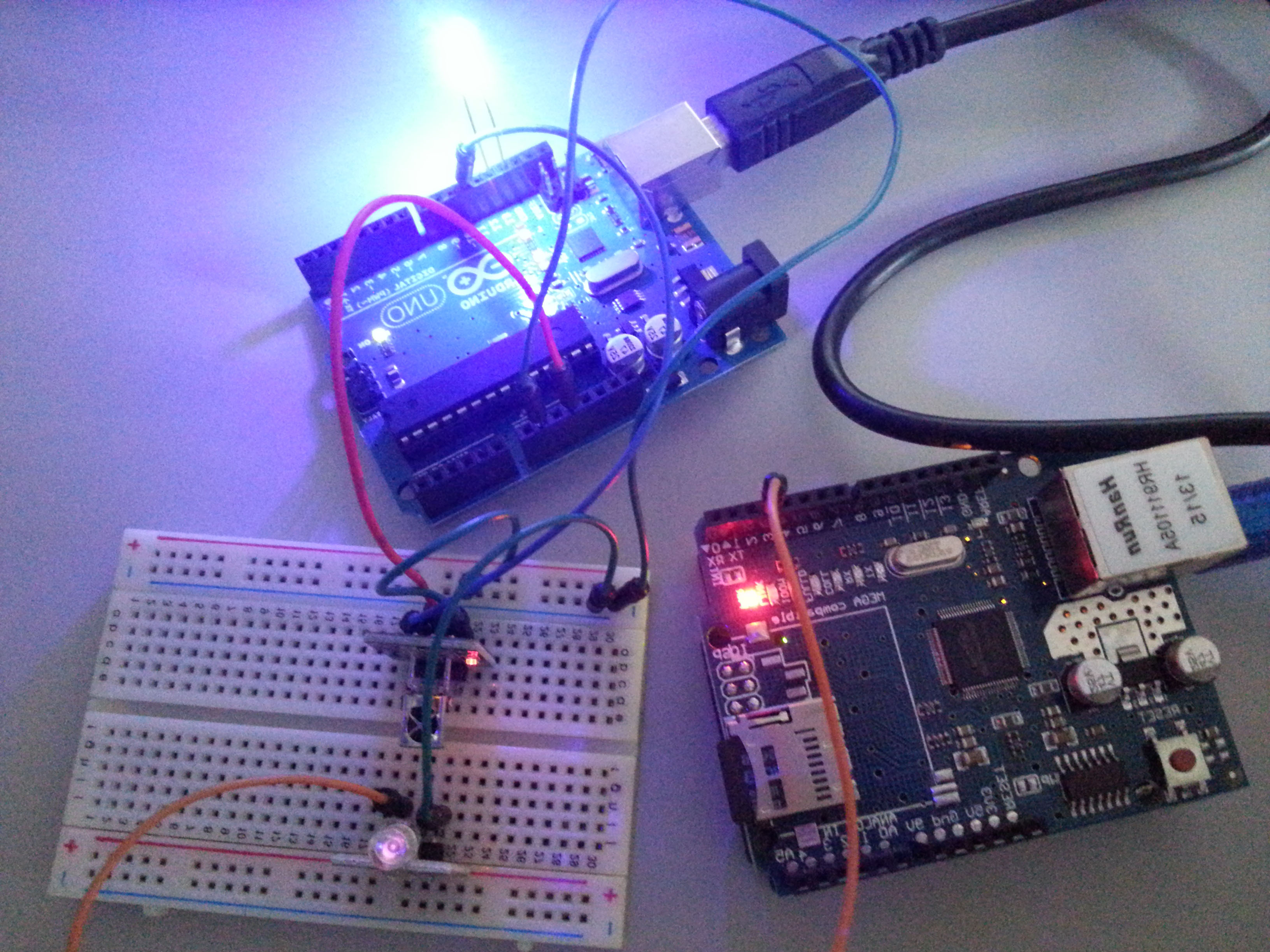 p/s: I added a LED on the receiving board to acknowledge my transmission successful. My sender board is an identical Arduino Uno but with an Ethernet shield on top of it. Notice how i place my emitter and receiver module facing each other openly, without blocking.
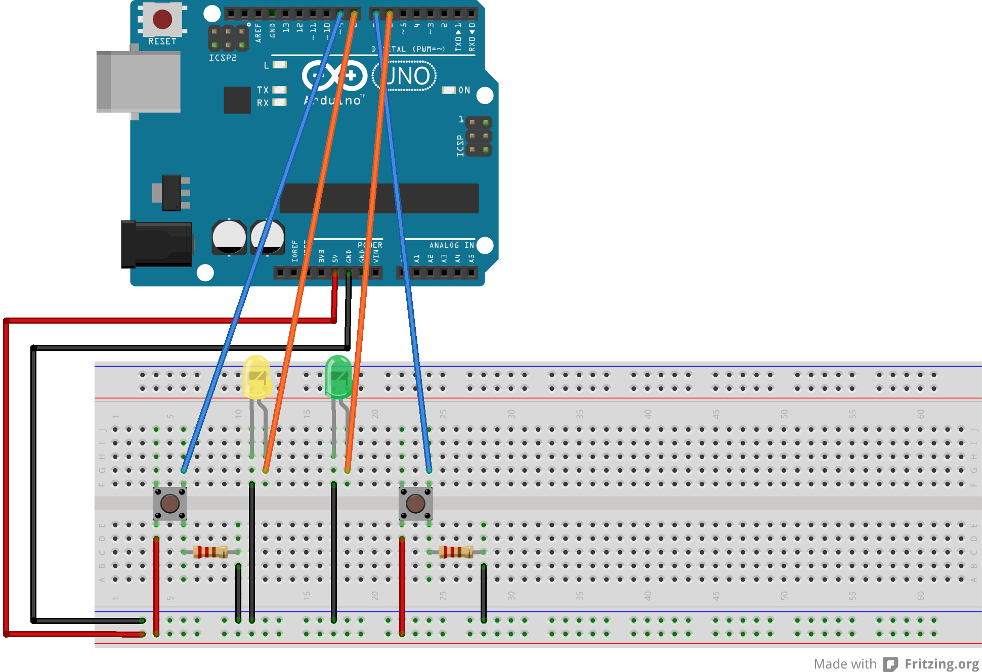
How about both on the same board?
I tried to put both sending and receiving module together on one Arduino board, hopping the sending signal can be received by the same board simultaneously, but failed. It seems like due to the single threaded nature of Arduino processor, we cant do these 2 things at the same time.
Googling reveal similar questions without answer:
http://forum.arduino.cc/index.php?topic=28745.0
Please let me know if you found ways to do this 😉
p/s: I added a LED on the receiving board to acknowledge my transmission successful. My sender board is an identical Arduino Uno but with an Ethernet shield on top of it. Notice how i place my emitter and receiver module facing each other openly, without blocking.
How about both on the same board?
I tried to put both sending and receiving module together on one Arduino board, hopping the sending signal can be received by the same board simultaneously, but failed. It seems like due to the single threaded nature of Arduino processor, we cant do these 2 things at the same time.
Googling reveal similar questions without answer:
http://forum.arduino.cc/index.php?topic=28745.0
Please let me know if you found ways to do this 😉