 Double check with your control panel -> Device Manager.
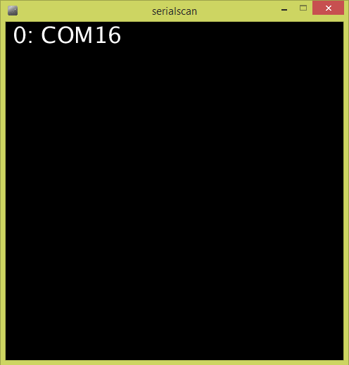
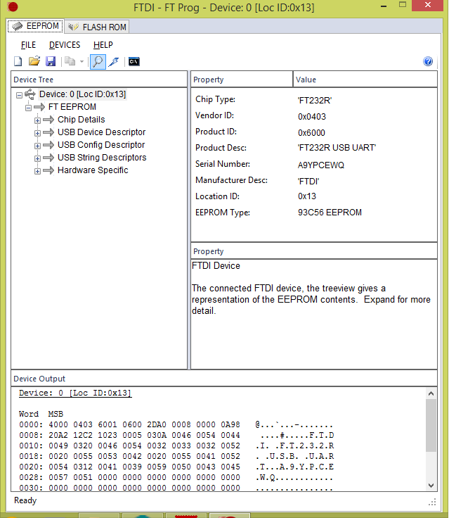
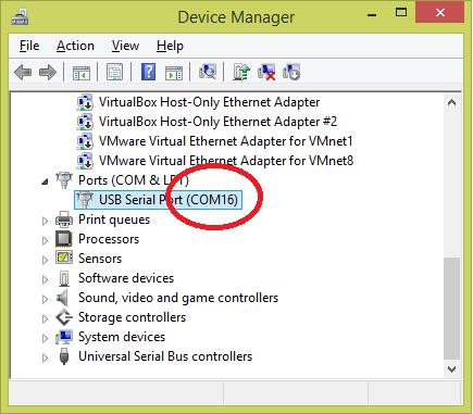 Device Manager show COM16 where our arduino board connected with, is match with index 0 in the processingScanner. So, the number/index to use in process is 0.
Double check with your control panel -> Device Manager.
Device Manager show COM16 where our arduino board connected with, is match with index 0 in the processingScanner. So, the number/index to use in process is 0.
Device Manager show COM16 where our arduino board connected with, is match with index 0 in the processingScanner. So, the number/index to use in process is 0.
Double check with your control panel -> Device Manager.
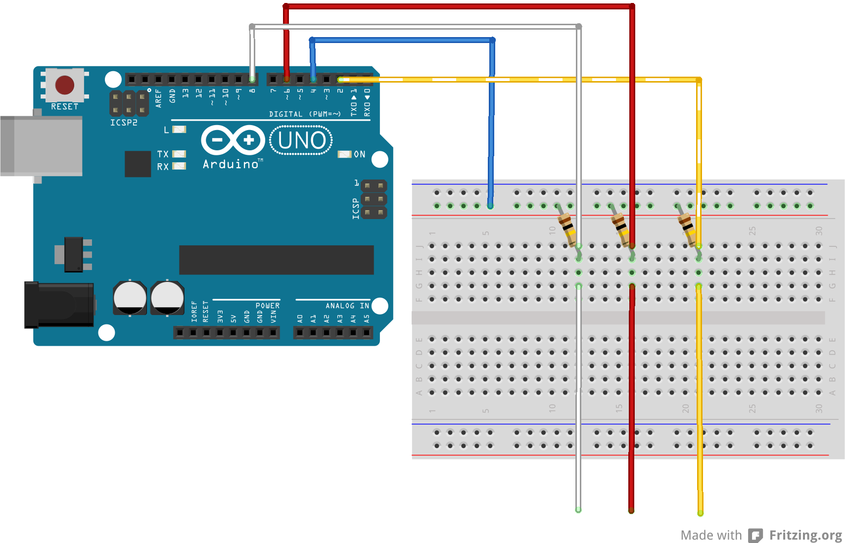
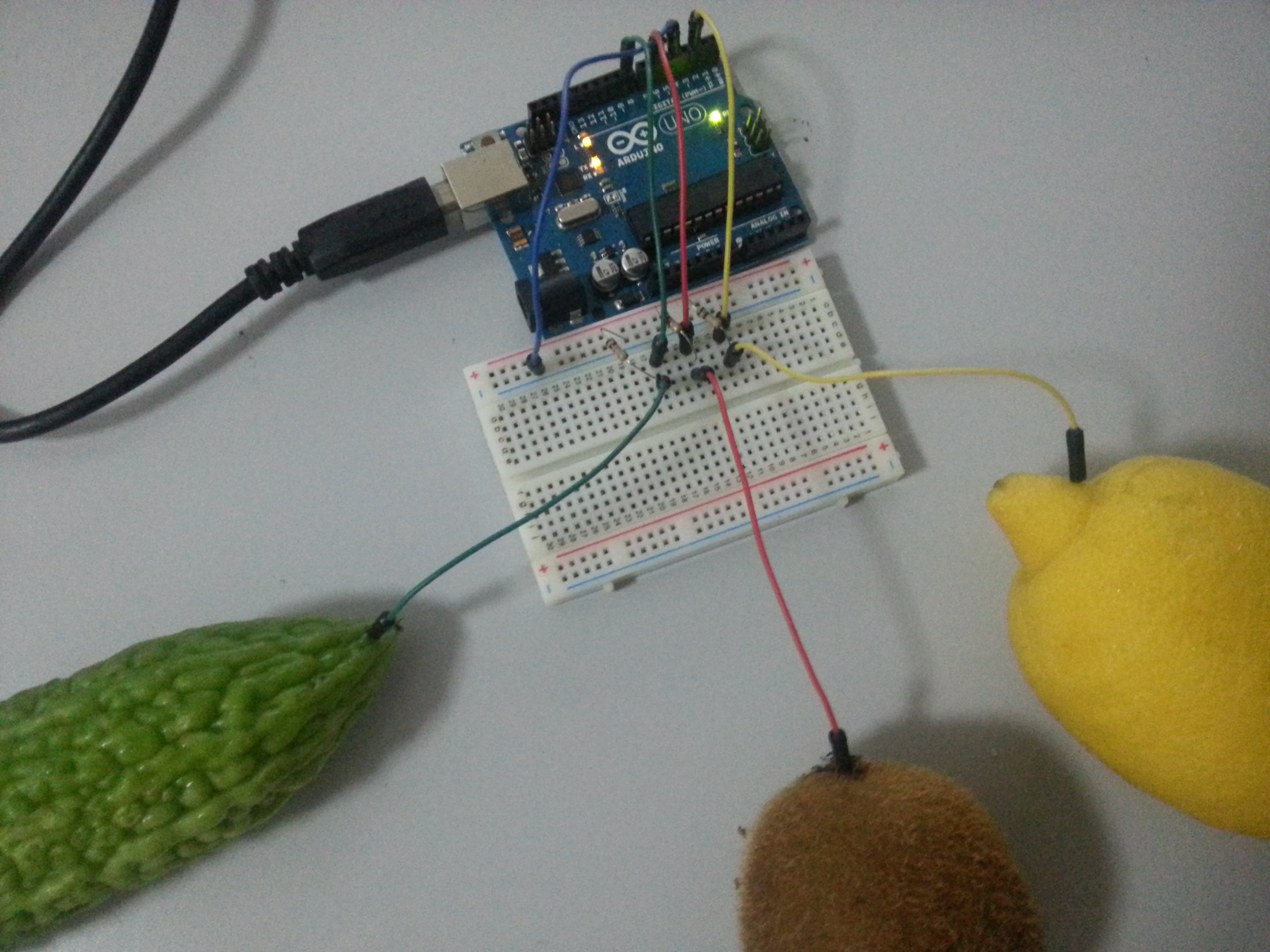
Device Manager show COM16 where our arduino board connected with, is match with index 0 in the processingScanner. So, the number/index to use in process is 0. 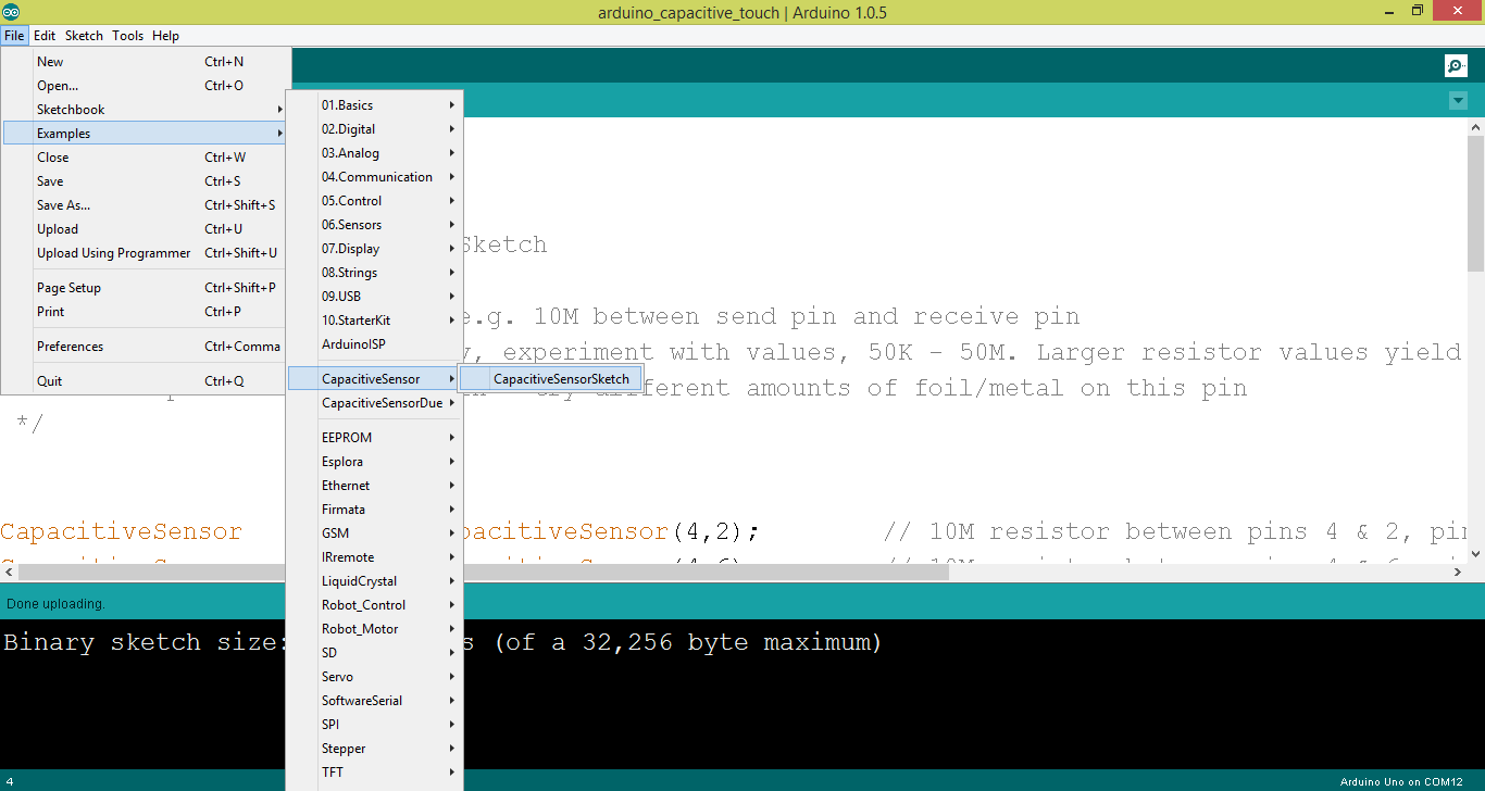 Then, construct a circuit with arduino uno board. The resistor I using here is 10k ohm but the best would be 1M ohm.
 You will need to upload the following sketches:
|
1 2 3 4 5 6 7 8 9 10 11 12 13 14 15 16 17 18 19 20 21 22 23 24 25 26 27 |
#include <CapacitiveSensor.h> CapacitiveSensor cs_4_2 = CapacitiveSensor(4,2); // 10M resistor between pins 4 & 2, pin 2 is sensor pin, add a wire and or foil if desired CapacitiveSensor cs_4_6 = CapacitiveSensor(4,6); // 10M resistor between pins 4 & 6, pin 6 is sensor pin, add a wire and or foil CapacitiveSensor cs_4_8 = CapacitiveSensor(4,8); // 10M resistor between pins 4 & 8, pin 8 is sensor pin, add a wire and or foil void setup() { cs_4_2.set_CS_AutocaL_Millis(0xFFFFFFFF); // turn off autocalibrate on channel 1 - just as an example Serial.begin(9600); } void loop() { long start = millis(); long total1 = cs_4_2.capacitiveSensor(30); long total2 = cs_4_6.capacitiveSensor(30); long total3 = cs_4_8.capacitiveSensor(30); Serial.print(total1); // print sensor output 1 Serial.print(","); Serial.print(total2); // print sensor output 2 Serial.print(","); Serial.println(total3); // print sensor output 3 delay(10); // arbitrary delay to limit data to serial port } |
 You may further enrich the output using processing + serial.
|
1 2 3 4 5 6 7 8 9 10 11 12 13 14 15 16 17 18 19 20 21 22 23 24 25 26 27 28 29 30 31 32 33 34 35 36 37 38 39 40 41 42 43 44 45 46 47 48 49 50 51 52 53 54 55 56 57 58 59 60 61 62 63 64 65 66 |
import processing.serial.*; int touch1Value = 0; // sensor 1 value int touch2Value = 0; // sensor 2 value int touch3Value = 0; // sensor 3 value int threshold = 30; Serial myPort; void setup() { size(800, 800); // List all the available serial ports println(Serial.list()); // I know that the first port in the serial list on my mac // is always my Arduino, so I open Serial.list()[0]. // Open whatever port is the one you're using. myPort = new Serial(this, Serial.list()[0], 9600); // don't generate a serialEvent() unless you get a newline character: myPort.bufferUntil('\n'); } void draw() { background(0); println("touch1Value:"+touch1Value+" touch2Value:"+touch2Value+" touch3Value"+touch3Value); if(touch1Value == 1) { background(255, 255, 0); } else if(touch2Value == 1) { background(255, 0, 0); } else if(touch3Value == 1) { background(0, 255, 0); } } void serialEvent(Serial myPort) { // get the ASCII string: String inString = myPort.readStringUntil('\n'); if (inString != null) { // trim off any whitespace: inString = trim(inString); // split the string on the commas and convert the // resulting substrings into an integer array: float[] touches = float(split(inString, ",")); // if the array has at least three elements, you know // you got the whole thing. Put the numbers in the // touchX variables: if (touches.length >=3) { touch1Value = touches[0] >= threshold ? 1: 0; touch2Value = touches[1] >= threshold ? 1: 0; touch3Value = touches[2] >= threshold ? 1: 0; } } } |
|
1 |
Serial sPort = new Serial(this, Serial.list()[portIndex], 57600); |
 So, this is my replied to them:
I give up on this order due to stupid people who tried to stop the earth from rotating.Wah damn mafan… come on, it’s just a beagleboard, i not ordering uranium! I will never recommend my frens, clients and students buy this item from Element14 Sg anymore.1. Yes, you may ship to either address.2. Fuck singapore custom. ask them get from Malaysia SSM. http://www.ssm.com.my/3. Everything is on wikipedia and google. http://en.wikipedia.org/wiki/Installation_art
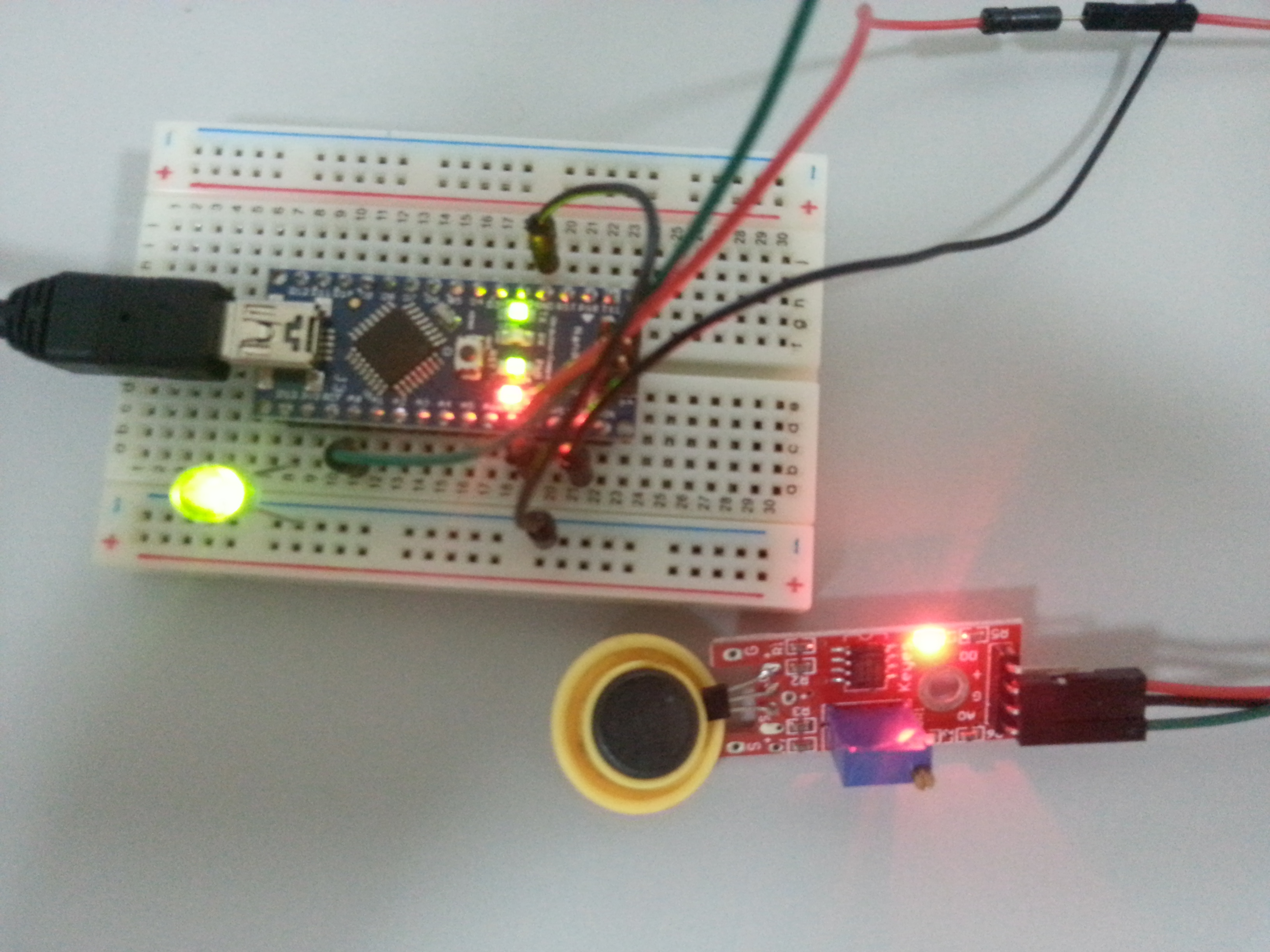 Meanwhile, I am playing with my new nano board. But the magnet I have here is not strong enough. It need to be very close to the sensor (like 1cm). Gotto order new rare earth magnet from dx.com then.
Simple code to output the analog in reading, and if less then the threshold, light the LED.
Meanwhile, I am playing with my new nano board. But the magnet I have here is not strong enough. It need to be very close to the sensor (like 1cm). Gotto order new rare earth magnet from dx.com then.
Simple code to output the analog in reading, and if less then the threshold, light the LED.
|
1 2 3 4 5 6 7 8 9 10 11 12 13 14 15 16 17 18 19 20 21 22 23 24 25 26 27 28 29 30 31 32 33 34 35 36 37 38 39 |
const int analogInPin = A0; // Analog input pin that the potentiometer is attached to const int analogOutPin = 9; // Analog output pin that the LED is attached to const int ledPin = 13; int sensorValue = 0; // value read from the pot int outputValue = 0; // value output to the PWM (analog out) int threshold = 515; void setup() { // initialize serial communications at 9600 bps: Serial.begin(9600); pinMode(ledPin, OUTPUT); } void loop() { // read the analog in value: sensorValue = analogRead(analogInPin); // map it to the range of the analog out: //outputValue = map(sensorValue, 0, 1023, 0, 255); // change the analog out value: //analogWrite(analogOutPin, outputValue); if(sensorValue < threshold) digitalWrite(ledPin, HIGH); else digitalWrite(ledPin, LOW); // print the results to the serial monitor: Serial.print("sensor = " ); Serial.print(sensorValue); Serial.println(""); // wait 2 milliseconds before the next loop // for the analog-to-digital converter to settle // after the last reading: delay(2); } |
Next, I try on the black board one. According to dx.com comment, this is a digital output and 10k resister is required between the 5v & signal pin.
 After placing the resistor in between, i getting reading of 1023 (off magnet) & 15 (with magnet). It is analog but the value only 2 state, so like the comment said, it did behave like digital. I can then use a map function to turn the value into either 0 or 1.
Next, I tried another sensor that looks exactly the same like above, except the packaging label with “analog hall sensor”. with the same circuit (with resistor removed) and code, this is what i observed:
After placing the resistor in between, i getting reading of 1023 (off magnet) & 15 (with magnet). It is analog but the value only 2 state, so like the comment said, it did behave like digital. I can then use a map function to turn the value into either 0 or 1.
Next, I tried another sensor that looks exactly the same like above, except the packaging label with “analog hall sensor”. with the same circuit (with resistor removed) and code, this is what i observed: